What is it and how it works
EXTERMINATE! If you like Doctor Who, you’ve heard this before. I’m going to talk about the effect behind a Dalek’s voice: ring modulation, also known as balanced modulation. Ring modulation is a signal processing function, a type of amplitude modulation (AM) that takes its name from the shape formed by the diodes on its analog circuit implementation. It was originally used for analog telephony.
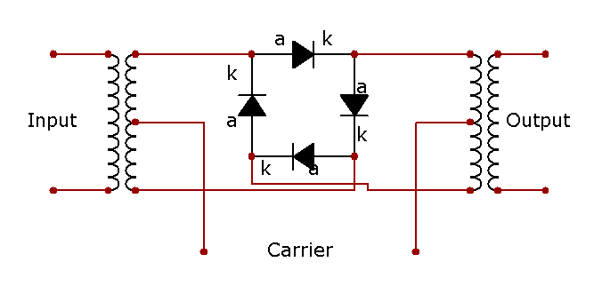 Fig.1 Ring modulator schematic (CC BY-SA 3.0 via Wikimedia Commons)
In ring modulation, the carrier signal is multiplied by the modulating signal. If the modulator is under the audible range, you will perceive it as a tremolo, however if the modulating frequency is within the audible range, it will produce sidebands that correspond to the sum and difference between the frequencies of each oscillator at the output. This effect can be used to modify sounds and produce robotic voices - like Daleks - and metalic, inharmonic chaotic tones, as I will demonstrate.
Let me show you what I mean by that: we’re going to multiply two [osc~] objects and take a look at the spectrum produced as a result.
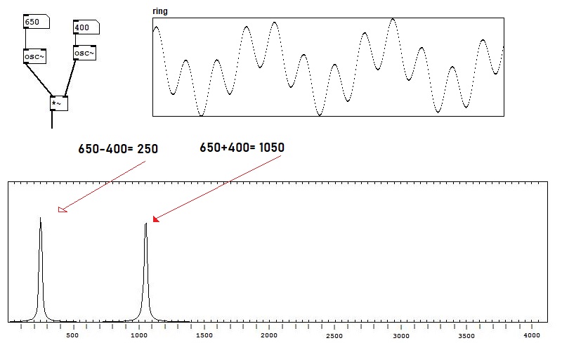 Fig.2 - Sidebands produced by ring modulation
Since we’re using 2 sine wave oscillators, the spectrum produced has 2 sideband frequencies. And as you can see neither of the original frequencies are present in the output spectrum.
You can use a microphone input to get that robot voice I initially told you about - your voice will be the carrier in this case. Let’s add an [adc~] and amplify the signal [*~ 10] and then multiply it by our modulator.
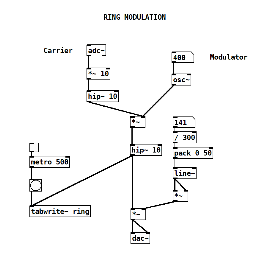 Fig.3 - Using a microphone as input
If the oscillators frequencies are harmonically related, ring modulation will produce harmonic partials. Let’s change our patch a little bit by adding another [osc~] and creating that relation to see what happens.
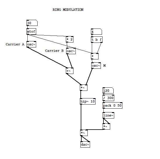 Fig.4 - Adding harmonic partials
I set Carrier A to MIDI note 30, which is equivalent to 46,25Hz (F#0) and Carrier B is twice the frequency, hence 1 octave up, 92,5 Hz (F#1). The modulator (M) is set to 4x 46,25Hz or 185Hz.
Now, I’ll take a break to explain something important if you’re not that familiar with Pd yet: in Pd, the cold inlet (the second one) doesn’t take effect until you change the value in the first inlet, so if I change the modulator frequency it won’t take effect until I change the carrier frequency. The way you fix that is by using [t b f] so that any time you change the modifier it will also send a bang to the first inlet, forcing the multiplication to happen.
That being said, let’s take a look at the spectrum:
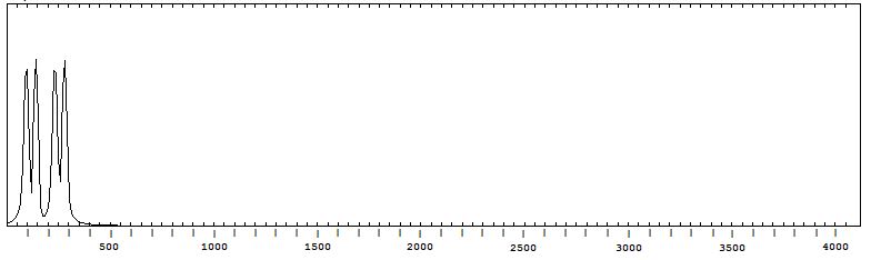 Fig.5 - Spectrum analysis of the product
What we have here are 4 partials: 1st: B-M = 92,5Hz (F#1) 2nd: A-M = 138,75Hz (C#2) 3rd: A+M = 231,25Hz (A#2) 4th: B+M = 277,5Hz (C#3)
Video demonstration
I encourage you to try ring modulation and see what kind of sounds you can produce just by using this effect, try using different waveshapes and see how you can produce complex spectra, like in the example below.
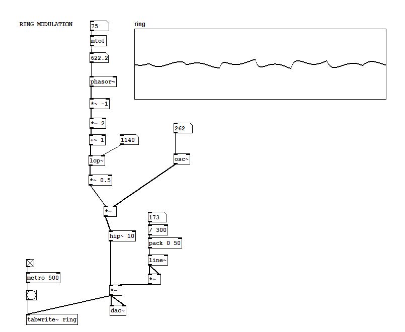 Fig.6 - Using a sawtooth as carrier
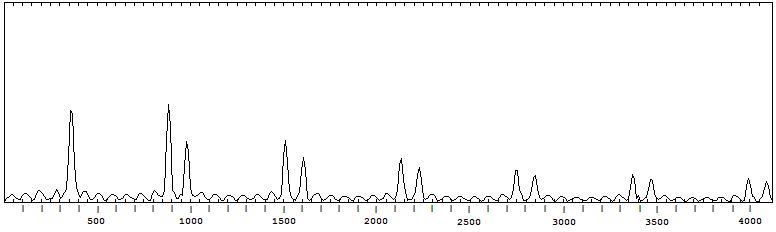 Fig.7 - More complex spectrum produced by ring modulation
If you want to learn more about ring modulation check the references section: lots of great resources!
References
Puckette, Miller. The theory and technique of electronic music. World Scientific Publishing Company, 2007.
Strange, Allen. Electronic music: systems, techniques, and controls. William C Brown Pub, 1983.
Aikin, Jim. Power tools for synthesizer programming: the ultimate reference for sound design. Backbeat Books, 2004.
FLOSS Manuals http://write.flossmanuals.net/pure-data/amplitude-modulation/
Wikipedia page https://en.m.wikipedia.org/wiki/Ring_modulation